


Obviously, the microcontroller (m/c) cannot drive the motor on its own, so the L293 driver is used as well. The m/c uses PWM to control the L293. When pin 10 of the L293 is high, pin 11 is also high and the motor is off. The lower the voltage on pin 10, the greater the difference created between pin 11 and Vp(=+5V), and the faster the motor runs.
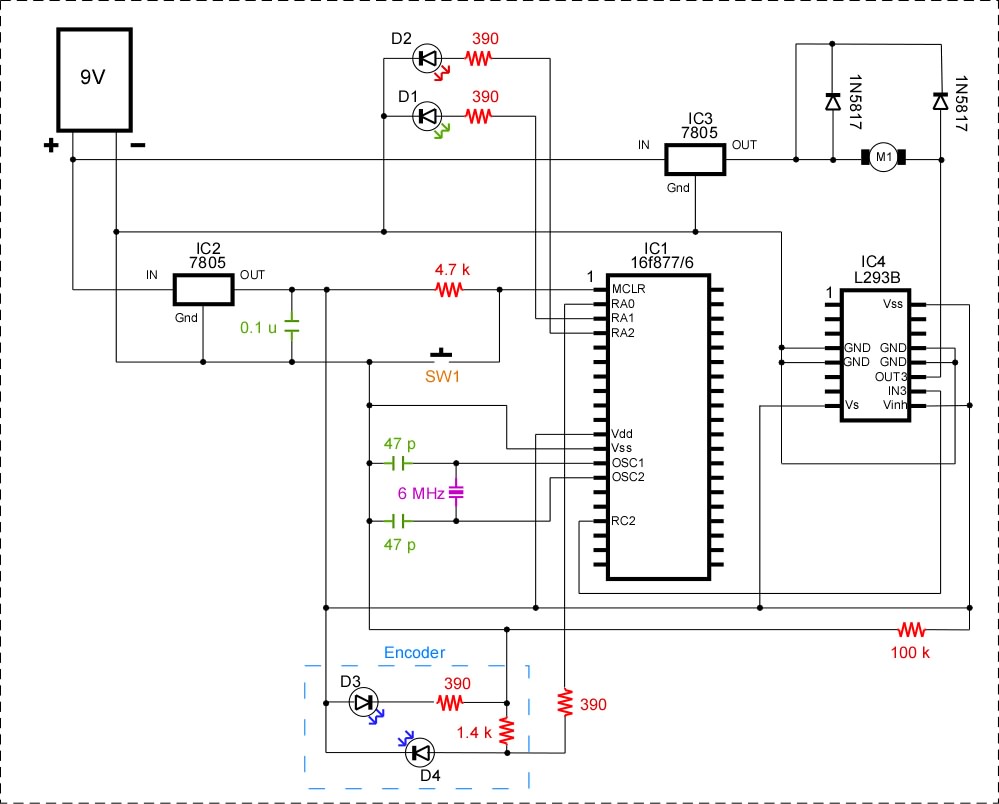
In Fig. 1 you can see the layout of the circuit used. There's more info on the home-made encoder here. The assembly code for the PIC 16F876 is available here.
When power is applied to the circuit, there is an initial programmed delay, during which the red LED D2 is lit. During this delay, the PWM output of the m/c on RC2 is high, so the L293's pin10 is high an the motor is stopped.
Then, the PWM is dropped to 1V, the voltage on the L293's pin 11 drops, and the motor starts. As the motor revolves, the encoder axle is also turned, producing pulses read by RA0 on the m/c. The m/c counts the pulses of the encoder, and when a programmed number is reached, the motor is stopped, by making the PWM high.