


The body, seen below, is made of LEGO bricks. These are extrmeley easy to use, can be put together and taken apart instantly, bond well and are quite light.
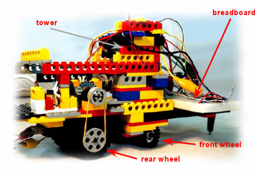
As can be seen, it's a simple design with a steering wheel in front and two drive wheels behind. At the front the breadbord can be seen on which I test the robot's circuitry. The "tower" is in fact the housing for the motor that turns the front wheel through the transmission system. The robot is equipped with two DC motors, one to drive the rear wheels and one to turn the steerable wheel at the front.
The one driving the rear wheels is a LEGO motor and actually includes a transmission of its own that gears down its speed and increases torque.
The motor for turning the front wheel is a cheap 6V DC motor that had only a smooth axle attached when I bought it. So I used a belt system to convey the motion of the motor to the LEGO gears I made the transmission with.
Back to the top.
The encoder is a device which measures the revolutions of the motors. The axle of the motor is connected to the axle of the encoder. There is one encoder for each motor. To be exact, the encoder actually produces a specific number of electric pulses for every rotation of its axle. These pulses are fed into the microcontroller that counts them. This way, the number of revolutions the axle has completed is known at any given instant in time.
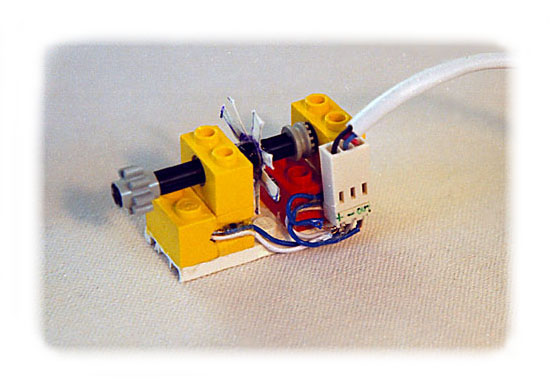
Taking into account the parameters of the transmission of the axle motion measured to the motion of the rear wheels for example, the distance the robot has travelled can also be computed. The speed of the axle connected to the encoder may also be measured, by numerically differentiating the pulse count fed to the microcontroller. This differentiation could be carried out in the microcontroller with the right programming, but could well be noisy - especially with the homemade encoder presented here!
The encoder schematic is shown below - click on it for a larger view. The two resistors are hidden inside the lego blocks. - This required a bit of digging first...
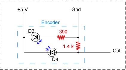
In the enocder, D3 is an IR LED, while D4 is an IR photodiode. The encoder is powered by two of the pins, while the pulses are produced on the "Out" pin. Note that when connecting the encoder to the microcontroller (m/c), I use a 390 Ohm series resistor.
Back to the top.
At the moment I'm working on the robot's first sensor. It's going to be an infrared proximity sensor. Basically, it will produce a signal when it senses an object at a certain distance in front of it.
This is done by emitting infrared light (not visible) in fron of the device. When there's an object close enough, the infrared light is reflected off it and heads back to the device. A infrared receiver (a photodiode) senses the light and produces a small current. This small current is essentially the signal used to tell the robot of the object's close proximity.
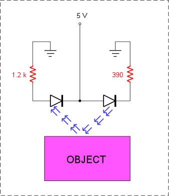
A problem with the simple sensor described above is that ambient light -light from the
sun, light bulbs, etc. - causes interference with the device. This happens bcause the
photodiode is sensitive mainly to infrared light but also to other wavelengths,
such as visible light.
Back to the top.
What is it?
The microcontroller is a minute computer that is the heart of all communication, control and data processing on the robot. The microcontroller I use is the Microchip PIC 16F877 and also the 16F876. These are not at all expensive to buy (about 8.5 Euros in Greece) and they have a very straightforward assembly language - although many programs exist that will allow you to write in C, or other languages.
PIC's and Linux
Microchip provides some very nice tools for the PIC, but they're only for Windows OS. But even if, like me, you work in Linux, then there are still ways to work with the PIC without leaving your favourite OS. The gputils package is well known - more details here.
I don't actually use gputils, but I do use gpsim, which is a software simulator for PIC m/c's. More details on gpsim here. For getting hex code from the assembly source files, I use the picasm assembler, from here. Another very popular assembler, called gpasm, is included in gputils.
Of course, to burn your code to the PIC you need a programmer, comprised of the software and the hardware. The hardware I use is Mario Catena's schematics from here. This is essentially similar to David Tait's Classic Pic Programmer, using a 7407 and transistor switches.
The software I use is David Tait's pp programmer, adapted for Linux, available from here. The Linux porting is the work of Chris Wilson. This is by far the fastest programmer I have ever worked with, on Windows or Linux. The programming hardware you can use with this software is pretty well limited to variations of David Tait's Classic Pic Programmer.
Finally, a great page on using PICs with Linux is here, written by Henry Palonen.
Back to the top.